Bolted Moment Connection Design Example
Shear at full section. Solution d022mm p1 65mm22d0 e155mm12d0 p270mm24d0 e250mm12d0 Selected Topics.
Aisc Steel Connection Design Software Cisc S16 Steel Connection Design Software
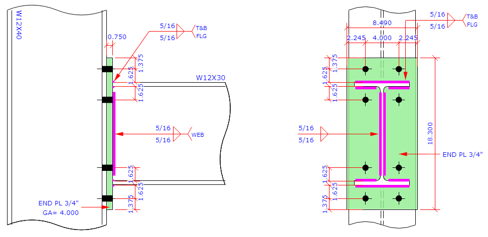
The most commonly used moment resisting connections are bolted end plate beam-to-column connections.
. Bolts at 90 or 100 mm cross-centres gauge. 2 Limit States- Shear Connections Bolt Strength Shear. Example IIB-1 Bolted Flange-Plate FR Moment Connection beam-to-column flange Given.
Example in the design of bolted tension members the net area is calculated assuming a suitable number and diameter of bolts based on experience. S275 or s355 fittings end plates splice plates and stiffeners. This joint should be able to transmit bending shear and axial forces.
3 4 nds equation 122-1 w 4366 compare to nds reference withdrawal design value table 122a w 437 lbsin. 20 mm end plates with m20 bolts. Resistance p tw resistance based on main member penetration lbs resistance 955 awc online connection calculator gives identical result of 955 lbs see nds table 1131 for application of additional adjustment f actors for connections.
Bolted eccentrically loaded connections can be analyzed in a manner similar to the methods of analysis of eccentrically loaded weldsIn certain ways the analysis is more evident given the clarity of how forces act upon each of the bolts. Through Plate Connection Example Bolt shear n RuΦrn Φrnper AISC table 7-1 n 63 --use n 8 two rows of four bolts Use 3 bolt spacing Use 1 edge distance AISC table J34 Use g 35 AISC table 1-1 21 Through Plate Connection Example 132014 8 Bolt bearing on. Eurocodes - Design of steel buildings with worked examples Brussels 16 - 17 October 2014 Example Single sided beam-to-column joint configuration bolted end-plate connection M V 15 3 IPE220 HEB140 120 60 10 30 80 30 240 4 M16 88 140 p60 u10 5 w To be evaluated.
Calculation Example Design bolted connection of tension plates EC3 Contents hide Description Selected Topics Check the following connection for tension force NEd600KN. Therefore it is necessary to verify the net area after designing the connection. All steel is grade A36 fy 36 ksi fu 58 ksi and bolts are grade A307 fy 50 ksi fu 65 ksi.
Fin plates at the beam flanges are with the thickness of 58 and the fin plates at the beam web are with the thickness of 38. Connection Length 50 in. In tests the first part of the moment rotational diagram.
The design model presented here relates to a bolted m om ent end plate. Let us design a bolted beam splice connection for a UB 533 x 210 x 101 kgm section subjected to the following ultimate limit state loads. Joel Berg 2018 07.
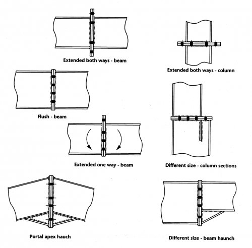
These are shown in the figure below. The joint is designed as a moment connection and is realized as bolted flange plate moment connection. M20 or m24 property class 88 bolts fully threaded.
AISC 13th Ed LRFD Bolted Moment Connections. Design moment resistance initial stiffness 0 1 10 10 M M J J. There are two general types of moment end-plate connections.
The following are generally recommended at least for initial design. The design strength of a moment connection may be. 18 Bolts Subjected to Eccentric ShearThere are forces that act directly and forces that are generated.
BOLTED CONNECTIONS II Version II 34 - 1 BOLTED CONNECTIONS II. Connection connecting square or rectangular hollow sections. The flange and web angle connection shown in Fig.
25 mm end plates with m24. It should be noted that continuity plates are not required resulting in a cheaper connection. Design Strength Single Bolt Capacity 080 080x080064 1 Design Spec.
Typical Bracing ConnectionsMenu Toggle Single Angles Double Battened Angles Double Starred Angles Single and Double Battened Channels Heavy-Duty Bolted Welded Heavy-Duty All Bolted Compression Struts with End-Plates Compression Struts with Splice Plates Girder Bridge Trusses Horizontal BracingMenu Toggle Horizontal Bracing Setting Out. Example of the components for a bolted beam to column connection is given in Figure 61. The design examples provide coverage of all applicable limit states.
Attempts to develop complex design procedures which can. There are cases where the axial force will actually REDUCE the design checks on a moment connection. 47 c e d f g i unstiffened column web in shear.
4 Bolt Shear Strength. In this post we are going to look at a design example of beam splice connection beam to beam connection using steel plates. Figure 62 gives an example of a beam to column connection and its moment rotational diagram.
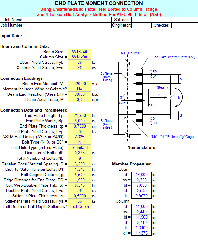
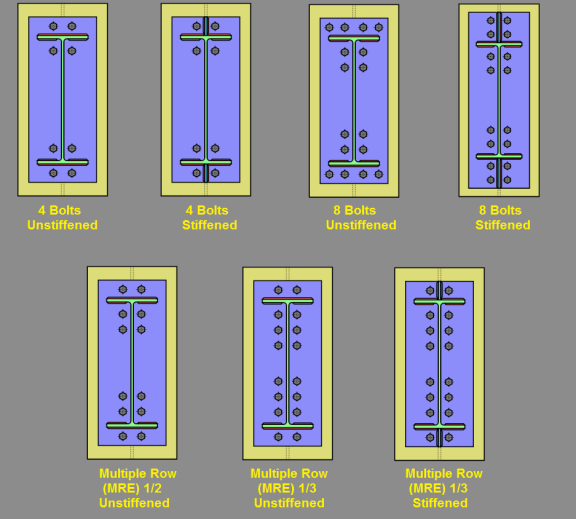
In this example the shear design strength is 1246 k and the maximum factored shear is 98 k. Design Examples V140 AMERICAN INSTITUTE OF STEEL CONSTRUCTION iii PREFACE The primary objective of these design examples is to provide illustrations of the use of the 2010 AISC Specification for Structural Steel Buildings ANSIAISC 360-10 and the 14th Edition of the AISC Steel Construction Manual. Analysis and design of 4 and 8 tension bolt moment connections per AISC 9th Edition ASD Manual Alex Tomanovich 2018 07.
Bolted-Welded Beam End Connection Using Single Clip Angle per AISC 13th Edition ASD. The moment design strength is 2138 k-ft and the maximum factored moment is 187 k-ft therefore connection capacity is adequate. This can happen for flange force failure modes.
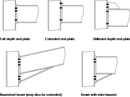
1a is an example of a typical beam-to-column moment connection. 2 Southern Pine main and side members Dead and construction live load controlsDead and construction live load controls Normal moisture and temperature 4 7 P P 3-58 4 4 4 4 4 4 7 3-58 23 38 P P. Flush end-plates Figure 12 and extended end-plates Figure 13.
Full depth end plate Extended end plate Stiffened extended end plate Haunched beam Instead of bolted beam-to-column connections welded connections can be used. Bolted Splice Joint Check What can this splice hold in tension. It is important for the novice to become.
Web Connection Design Force Moment. A flush end-plate is one in which the end-plate does not extend beyond the flanges of the beam section and all rows of. Slip-critical strength of the connection 24 x 924 kips 2217 kips Minimum edge distance Le 1 in.
Assume 1 diameter x 5 long bolts 2x12 No. Design a bolted flange-plated FR moment connection between a W1850 beam and a W1499 column flange to transfer the following forces. Calculates moment connection using flange plates not end plates.
M Vuwxe Muw Vertical Force. Bolts at 90 mm vertical centres pitch.

Design Checks For Moment Connections

Moment Resisting Connections Steelconstruction Info
End Plate Moment Connection Spreadsheet

Moment Resisting Connections Steelconstruction Info
Moment Resisting Connections Steelconstruction Info
Moment Resisting Connections Steelconstruction Info

Moment Connections Calc Them All Idea Statica
Design Checks For Moment Connections

Example Of The A All Bolted Split Tee Connection And B Through Beam Download Scientific Diagram
0 Response to "Bolted Moment Connection Design Example"
Post a Comment